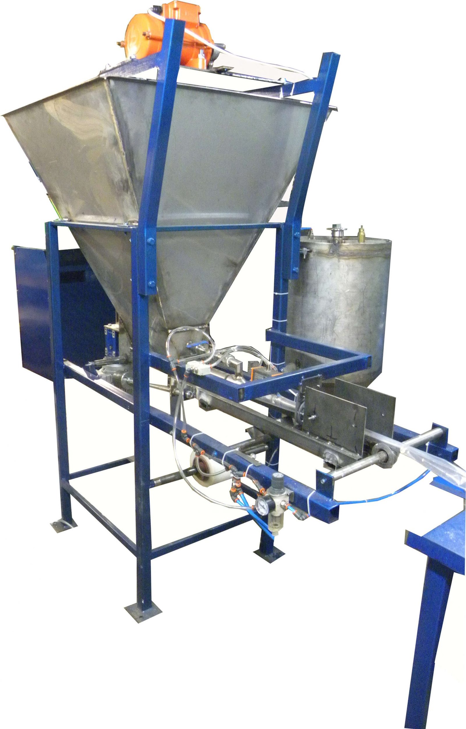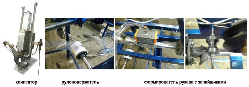


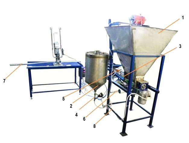
The line is designed for the production of flexible casings from polymeric film materials, the portioned filling of these casings with one or two components (with separating barriers), the application of metal clips, and the separation into individual measured units.
Technical specifications:
Product – any semi-viscous mixture (abrasive, non-aggressive). Packaging material – HDPE; LDPE, 80 µm to 100 µm thick.
Product technical specifications*
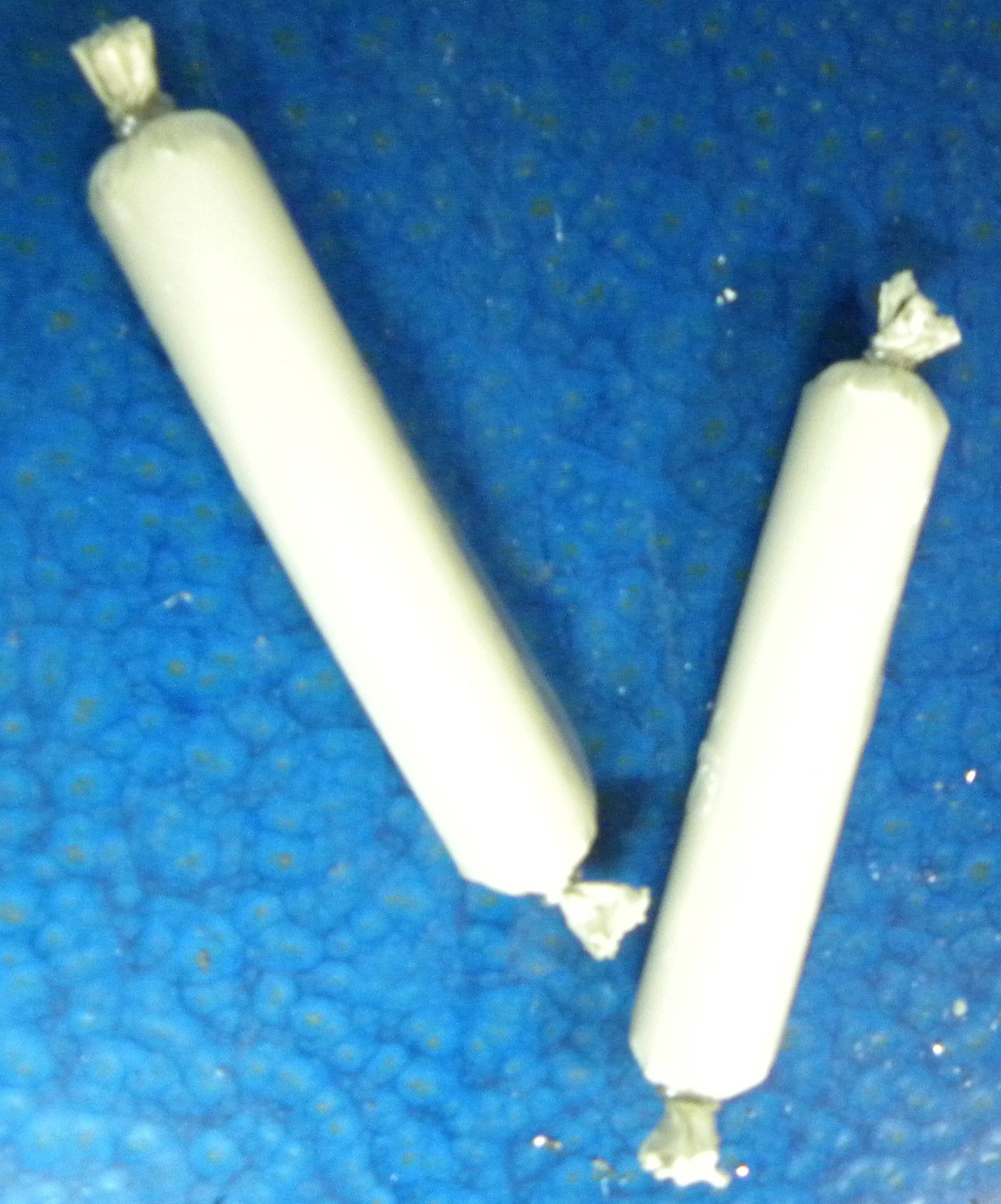
- length – 300 – 900 +/- 5 mm;
- diameter – 25 +/- 1 mm;
- weight – 300 – 900 g;
- clip – metal (on both ends).
- capacity – up to 5 units/min.
*It is possible to manufacture a similar line, tailored to the customer’s individual requirements.
Line specifications
Screw feeder for metered product supply from the storage hopper – 3.
- power supply – 380 V; 50 Hz; 1.1 kW.
- control (start/stop) – via sensors
- hopper capacity – up to 250 L.
Volumetric-type dispenser – 4.
- Type: volumetric.
- Dose volume: 5–20 g.
- Margin of error: +/-5%.
- Drive: pneumatic.
- Power supply: 220 V; 50 Hz; 0.25 kW. 6 atm / 60 L/min.
- Hopper capacity: up to 60 L.
Sleeve former with sealers – 5.
- Heating type: impulse.
- Seal type: 3 mm sealing seam.
- Seal length: up to 900 mm.
- Number of seals: 2 (opposing).
- Drive: pneumatic.
- Film advance: automatic.
Roll holder – 6.
- quantity – 1 pc.
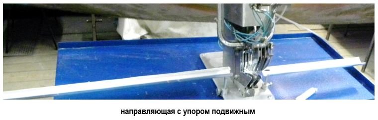
Guide with a movable stop – 7.
- quantity – 1 pc.
Frame – 8.
- quantity – 1 pc.
Two-line clipper – 9.
- quantity – 1 pc.
- bracket – metal
- number of grooves – 2
- blade – sickle-shaped, 1 pc.
- drive – pneumatic
- control – manual, via push-buttons
Overall dimensions of the unit, not exceeding 2600×700×1500 mm.
weight – up to 180 kg.
Operator – 1 person + assistant.
Equipment components and parts that come into contact with the product are made of corrosion-resistant materials.
The design allows for rapid disassembly of the units for sanitization.
Purpose
The line is designed for the production of flexible casings from polymeric film materials, the portioned filling of these casings with one or two components (with separating barriers), the application of metal clips, and the separation into individual measured units.
Areas of application for the line
Production of capsules for anchor bolting, and packaging of construction mixtures and other non-food materials.
Line components:
- storage hopper for the first type of product
- storage hopper for the second type of product
- dispenser for the first type of product
- dispenser (needle-type feeder) for the second type of product
- sleeve former with sealing units
- roll holder
- guide rail with an adjustable stop
- frame
- double-line clipping machine
Operating principle
The line consists of:
- a unit for forming and filling with process materials, and
- a unit for determining the length of the ampoule, applying clips, and cutting.
The unit (1) consists of a welded metal structure, which houses the following components:
A hopper (1) equipped with a screw feeder (3) and an electric drive for dispensing the first type of product.
At the outlet of the screw feeder, there is a forming tube (mandrel) fitted with a collar-style sleeve former and guide rollers.
Positioned above the forming tube are a heated sealing roller (constant-heat sealer) and a cooling roller for the seal.
Mounted on the main metal frame (8) is a second hopper (2), featuring a valve system and a needle-type feeder (4) for filling ampoules (or tubular casings) with a second type of product. The needle-type feeder (4) is positioned above the dispenser’s forming tube.
Located at the bottom of the frame are a film roll holder and alignment guides for the film feed.
The line also includes a free-standing table, which holds a double-clipper (9), the line control unit, and the compressed air distribution manifold.
Film from the roll holder passes through a system of alignment rollers and enters the sleeve former, wrapping around the forming tube; the needle-type feeder is positioned between two layers of the film. As the film is pulled along the forming tube, the sealing head roller moves across the film, creating two parallel seals spaced 16 mm apart.
Upon an operator command, the screw feeder drive is activated, and the product from hopper (1) is fed through the forming tube into the main cavity of the polymer sleeve.
Simultaneously, the second type of product is dispensed from hopper (2)—driven by compressed air pressure—through the needle-type feeder and into an outer cavity within the sleeve, formed between the two seal lines. Driven by the pressure of the product being fed and guided by the operator, the filled casing moves onto a table equipped with a clipping machine.
Once the product reaches the desired length, the operator pulls down the handle of the clipping machine; this compresses the casing, applies two adjacent clips, and cuts the finished, measured segment of the product.
The process is then repeated.
Additional information
12-month warranty
Post-warranty service